Edwin E. Ritchie Observatory Telescope History
The 27.5″ Mirror
After the incorporation of BPAA by Ed Ritchie, Mac Gardner and John Rudolph, the founders were able to obtain two extremely high quality Zerodur mirror blanks from the Boeing company. These mirror blanks were surplused from a “Star Wars” project. One mirror was 40″, the other 27.5″. The 40″ mirror would have produce a telescope that exceeded local height restrictions. Ultimately, it found a good home at the University of Arizona. The BPAA retained the 27.5″ mirror to build the primary telescope of our association.
The grinding and polishing took approximately one year. First, about 0.5″ in depth was spherically diamond ground from its surface to eliminate existing ball depressions. Then ceramic laps were used in four stages of grit to smooth the spherical surface. An 18″ spherometer was used to extremely accurately monitor both sphericity and focal length. After sphericalization with 8 micron garnet, pre-pitch laps were made using the mirror as a molding template and final spherical polishing was begun on the mirror.
After almost perfect spherical polishing was completed, parabolization or figuring was begun by deepening the center of the mirror 0.00045″. This was done totally with a smaller pitch lap. Both Ronchi and Foucault testing were used to monitor the figure. The final tests were completed by Foucault technique using zonal masks with Bob Mathews’ help in the reading and analyses.
A 4″ outer diameter tubular hole was ground leaving a 3.5″ diameter plug. This plug was left in, surrounded by plaster during the entire grinding and polishing operation. After completion of the mirror, this plug was removed by grinding a tiny amount of holding glass out from its backside with diamond cutters furnished by Molly Griest.
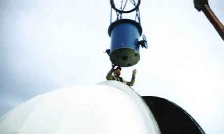
The mirror was then carefully crated and taken to California to be vapor deposit alumized and “enhanced”. The mirror was installed in the telescope and the telescope was moved to the dome in December of 1997.
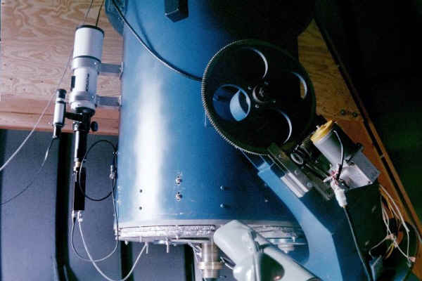
The Telescope Structure
The telescope base and the drum and fork were built during this same period. Quarter inch steel plate donated by Russ Trask was used in its construction and it was flame cut by Johnnie Magnuson. Most of the extensive welding was done by Butch Bretsen. All of the columns, including the central fork column are very heavy steel. Precision bearing surfaces were machined into the columns before welding. Huge Timkin tapered bearings were used on the main fork column with a take-up nut at the bottom of the column. An internal conduit was placed inside the structure and pre-wired for control wiring. The three major base units, which include the base, the drum and the fork, weigh more than 1000 pounds. The base has mounting feet which match the bolts in the concrete pad at the Battle Point Park Observatory
Gears were made – one of 28″ diameter with 360 teeth and one of 14″ diameter with 180 teeth for the polar and declination axes. The two main gear blanks, from Alaska Copper and Bronze, were accurately jet-cut by Micro Jet of Monroe. Indexing plates were first made on the milling machine using a precision rotary table, one with 360 holes, one with 180 holes, to control the spacing of the gear teeth. I then machined these, including the worms, using #4 pitch teeth.
The telescope tube, the final unit in our telescope, was made by rolling 1/8″ aluminum plate into a cylinder about 30″ in diameter and 36″ long. Both side yoke bearings were fit and bolted into this unit. A 5/8″ back plate was welded to the back of this unit with 16 threaded mounting holes. This unit is precision-matched to the cell which holds the mirror. This cell consists of two discs of 5/8″ aluminum. One is bonded to the mirror with nylon spacers and silicone. The other one is mounted to the telescope tube, and the two of them are interlocked with four special mirror adjustment units. This cell weighs about 100 pounds and the mirror weighs about 200 pounds. In addition, there are 18″ diameter 1/2″ thick steel counterbalance discs which bolt to the back of the cell. The front of the optical tube assembly is composed of an aluminum truss tube structure. The end of the truss tubes are bolted to a ¼” thick aluminum ring which in turn supports two more similar rings which can rotate as a unit about the optical axis. These last rings contain the spider, the diagonal flat and the focuser. A CCD or other camera may be installed in the focuser in place of an eyepiece.
The Drive System
Note: The declination bearing system and the drive gear and worm were replaced in 2018-19.
Both right ascension and declination axes were originally driven with #34 series stepping motors with worm gear reduction. These stepping motors were controlled by ‘Sky Probe 1000’ software and a 486 computer. The stepper motor control system was plagued with problems and eventually replaced with a servo motor control system during the winter of 2004-2005. The servo motor system uses software developed by Mel Bartels and motor controllers and a wireless hand pad developed by Dan Gray. The control system is described in detail at their websites: http://www.siderealtechnology.com/ and http://www.bbastrodesigns.com/BBAstroDesigns.html Servo motors offer a wider range of speeds and smoother motion. They also do not suffer from stalling due to low torque at higher speeds. The trade-off is that they require more sophisticated control software. That software is now available to the amateur astronomy community in a way that it was not available when the Ritchie telescope was first built. The servo system is controlled by a desktop PC computer running planetarium software. We most often use the program Cartes du Ciel but there are several alternatives available that can easily be installed and used to control the telescope. These programs allow ‘point and click’ control of the telescope and give a graphical feedback of the telescopes pointing coordinates to the user.
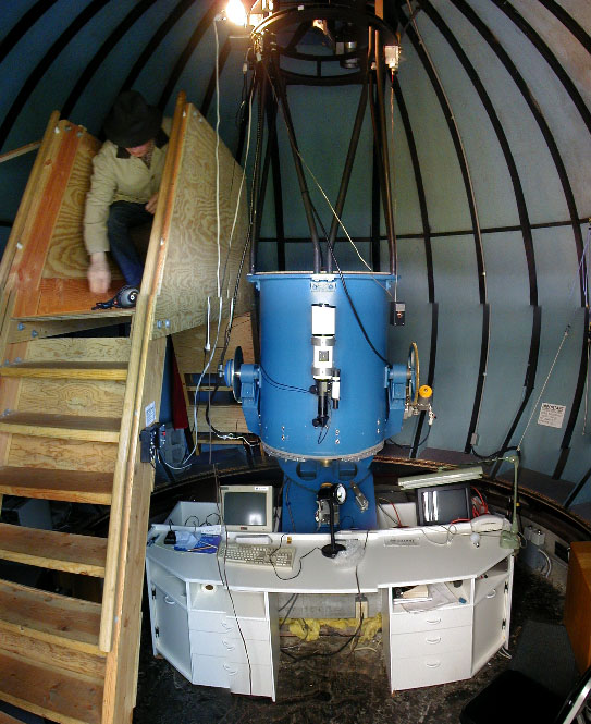
The Completed Telescope
The telescope was completed and installed in the dome in December of 1997. However “completed” is a misleading word when used for a telescope. As with a wooden boat, a telescope always needs maintenance. In addition, as technology changes, dramatic improvements become possible. For these reasons, we can expect that there will always be work to do in maintaining and upgrading the telescope. Ed Ritchie passed away shortly before the telescope was installed in the dome. He left behind very little documentation of the telescope design and construction. One on-going project is the retroactive documentation of the design in a detailed computer model of the telescope. That information is useful to have not only as a tribute to the work of Ed Ritchie but also because it makes it easier to carry out upgrade and maintenance work.
Observatory Dome
The observatory dome is constructed of ¼” plywood formed over bent aluminium tubing. The wood is coated on the outside with a weather-resistant white paint. The dome is mounted on large rubber casters that roll on a circular track allowing the dome to rotate 360 degrees. There is a slit with a shutter that opens to the sky. Both the dome and the shutter are motorized.